This is an old revision of the document!
Install IPFire on a Raspberry Pi CM4 on DFRobot Carrier Board over Serial Console
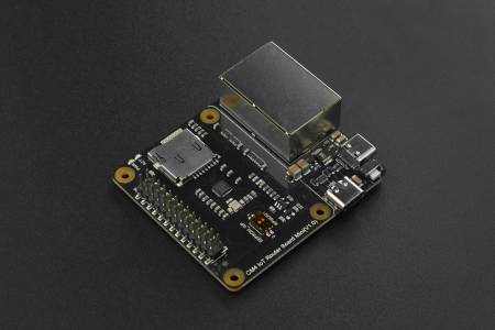
 This tutorial covers how to install a IPFire Firewall on to a Raspberry Pi Compute Module 4 that is carried on DFRobot's Router Carrier Board Mini using a serial console.
Disclaimer: all provided links in this article aren't sponsored!
→ IPFire's wiki can be found here.
→ And the DFRobot's wiki here.
Preparation / Requirements
- SD-Card (32 GB) + SD-Card-Reader
- Raspberry Pi Compute Module 4 (4GB RAM recommended)
- Jumper Wires (Female to Female)
- Official Raspberry Pi USB-C Powersupply (CM4 requires 5V 3A!)
- Configured and running Raspberry Pi (either with SSH-access or working display output)
Depending on your Setup:
- HDMI-Cable
- Keyboard
Download and flash the Image to the SD-Card
Download the aarch64 Flash Image from IPFire's webpage: ipfire.org/download.
Then flash the Image on another computer to the SD-Card. Therefore you can use Win32DiskImager (Windows), the official Raspberry Pi Imager (Linux, Windows and MacOS) or BalenaEtcher (Web, Linux and Windows).
- The compressed IMG is required, the ISO image will not work!
- If experiencing boot issues when using newer hardware revisions have a look at the official IPFire wiki: wiki.ipfire.org!
Before ejecting the SD-Card perform the following changes:
→ Enable the serial console: add (if not present) enable_uart=1 to config.txt.
→ Check if SERIAL-CONSOLE in uENV.txt is SERIAL-CONSOLE=ON.
Connect both Pi's with jumper cables

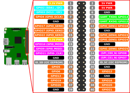
 Now connect the following pins on your carrier board's GPIO and your second Pi's GPIO with three jumper wires (female to female):
| Carrier Board (CM4) | 2nd Raspberry Pi | Use |
|---|---|---|
6 | 6 | Ground |
10 | 8 | Receive and send |
8 | 10 | Send and receive |
When connected properly you can power up the carrier board.
(It is recommended to first power up the second Pi and start the serial console before powering up the carrier board.)
Images sourced from siocours.lycees.nouvelle-aquitaine.pro and wiki.dfrobot.com - CM4 DFRobot Carrier Board
Open serial console using screen
Before you can open a serial connection: serial console must also be enabled on the Pi from which you wish to connect. Therefore check if your /boot/config.txt contains enable_uart=1. If not, add it at top (!) and reboot.
config.txt to get a human-readable console:
dtoverlay=pi3-disable-bt
dtoverlay=pi3-miniuart-bt
In general there might be issues with newer versions of the Raspberry Pi, therefore consider using an older version as second device. Additionally do not dis- and reconnect to a running console session, otherwise your console might not be readable anymore for this session.
Then you can execute the follwing command from the second Pi to connect to your serial console. It doens't matter if you're using an attached keyboard and monitor or a SSH-connection.
screen /dev/ttyS0 115200
→ you might install screen befire by running the following command:
sudo apt install screen
Finally perform the setup of IPFire as usual!
With Ctrl+A and D you can quit the screen-session.
Select correct boot method
When booting for the first time, there will be three entries in the grub bootloader.
Select the 3rd option, that contains serial console!
Adjusting interfaces (important!)
As described also in this blog post in IPFire's official forum, there are assigment issues with the carrier board's NICs. It seems that the second PCIe NIC gets a self-assignet MAC everytime the device boots up. This is followed by the host OS no longer recognizing the NIC. To solve this issue there is a more or less fancy workaround:
First completely shut down your device! This is important because by doing this, all NICs will be reinitialized!
Then reboot it and figure out which NIC causes the error therefore execute the following command:
ifconfig -a
It will print all ethernet devices, no matter if active or inactive.
The output should look like anything of this: no matter if selected the red or the green interface to be on the Pi's built-in NIC:
eth0:
[...]
lo:
[...]
red0:
[...]
eth0:
[...]
lo:
[...]
green0:
[...]
No matter if selected the red or the green interface to be on the Pi's built-in NIC, you will have an “unassigned” eth0 interface, which is the second PCIe NIC. To make your now unassigned interface persistent after future reboots, add eth0 to IPFire's ethernet config:
- Case 1: The red interface should be on the second NIC:
- Case 2: The green interface should be on the second NIC:
Verify your settings by running the following command:
cat /var/ipfire/ethernet/settings
GREEN_DEVGREEN_DESCRIPTIONRED_DEVRED_DESCRIPTION
The device whose description starts with pci: Realtek Semiconductor Co., Ltd. RTL8111/8168/8411 should have the […]_DEV set to [..]_DEV=eth0.
Example:
→ if GREEN_DESCRIPTION would start with pci: Realtek Semiconductor Co., Ltd. RTL8111/8168/8411, then GREEN_DEV should be GREEN_DEV=eth0
Apply your changes either by rebooting or reinitializing the network manager:
/etc/init.d/network restart
Resources used: cyberciti.biz - linux serial console, scribles.net - uart communitation between to Raspberry Pis and wiki.ipfire.org - Raspberry Pi 4 Model B